09 Nov Bridge saws – main square (re)calibration
How to (re)calibrate main-square reference profiles enforcing their position to be perpendicular to cut direction.
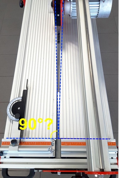
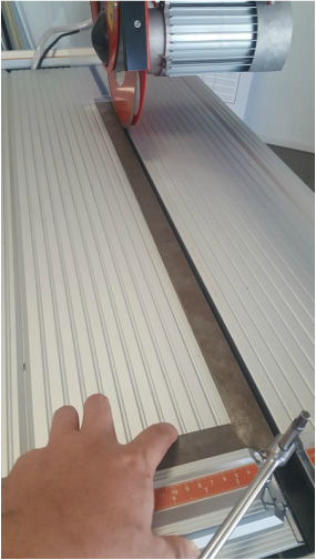
The problem
Cutting head’s (blade’s) movement is rectilinear, yet cut happens somewhat slantwise. This is due to main-square reference profile’s position (either, or both) not being perfectly calibrated anymore.
The solution
- Check left main-square profile’s calibration
- If needed, recalibrate left main-square profile’s position
- Check right main-square profile’s calibration
- If needed, recalibrate right main-square profile’s position
Required tools
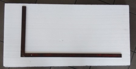
- A 90° mechanic’s square, of adequate size and in good conditions
- A size 6 Allen key
- Cyanoacrylic glue
Warning: a cheap, wooden, carpentry square tool is not adequate for this job. A good quality, iron/steel, mechanical square tool is required.
1. Check left main-square profile’s calibration
1.1
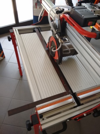
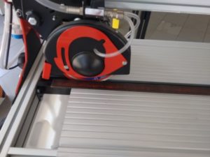
Lay the square tool onto the machine’s work table. Make sure that its short leg fully contacts onto left base-square profile.
1.2
Keeping engine OFF, slide the square along left base-square profile, bringing its long leng towards the blade until just a few millimiters distance from it. It’s important that the square’s long leg is brought very close to the blade, yet not in contact with it – just 1 or 2 millimiters distance is OK.
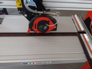
1.3
Keeping the engine always OFF, slide the cutting group all along the bring, from one end to the other of its allowed run. Observe the distance between the blade and the square’s long leg: it should stay unmodified during the whole operation. Structural tolerace is +/- 0,5 mm.
Should the distance between the blade and the square’s long leg be different at one end of the head’s run then at the other end, this is the signal that left main-square profile’s position must be adjusted.
2. Recalibrate left main-square profile’s position
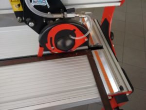
2.1
Bring the square’s long leg in contact with the blade. Its short leg will consequently be unable to fully contact left main-square profile. The picture shows a deliberately excessive case.
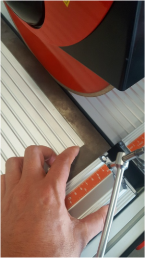
2.2
Unscrew left base-square profile’s Allen fixing screw, unlocking its position.
Bring the square’s short leg in full contact with the unlocked left profile. Holding the two elements together with a hand, tilt the group (square’s left leg + left main-square profile) until the square’s long leg is perfectly parallel to the blade – checking that such parallelism stays unmodified while sliding the cutting head from one end to the other of its allowed run space.
Lock the newly found calibrated position by re-tightening left base-square profile’s Allen fixing screw.
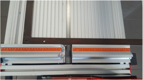
3. Check right main-square profile’s calibration
3.1
After checking left main-square profile’s calibration – or re-calibrating it if needed:
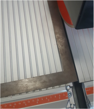
- bring square’s long leng in full contact with left main-square profile and check that it also results in full contact with right main-square profile.
- bring square’s long leng in full contact with right main-square profile and check that it also results in full contact with left main-square profile.
If both check above are positive, then right main-square profile is also calibrated. Otherwise its position needs to be adjusted.
4. Recalibrate right main-square profile’s position
4.1
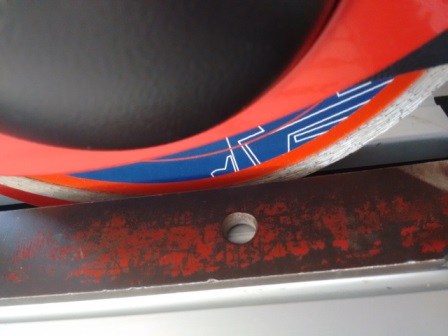
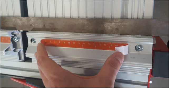
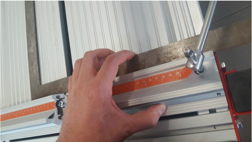
Unscrew the two Allen-head screws holding right main-square profile in position, unlocking it.
The screws are hidden under the orange stick-on calibrated ruler. To access them you need to lift the ruler’s ends, even without fully removing the ruler.
4.2
Bring the square’s long leg in full contact with left main-square profile.
Now bring right main-square profile – which is unlocked and free to move – in full contact with the square, always ensure to never lose contact with (locked) left main-square profile.
Lock the newly found calibrated position for right main-square profile by re-tightening its Allen screws.
Re-stick the ruler in place helping yourself with just a couple of cyanoacrylic glue drops.
Procedure’s differences accross Ghelfi machine models
All steps and instructions above substanstially apply to all bridge-structure Ghelfi machine models.
The sole notable difference accross various model families stands in main-square profile fixing screws positions.
Instructions above directly apply to Ghelfi Squalo and miniMAX family models.
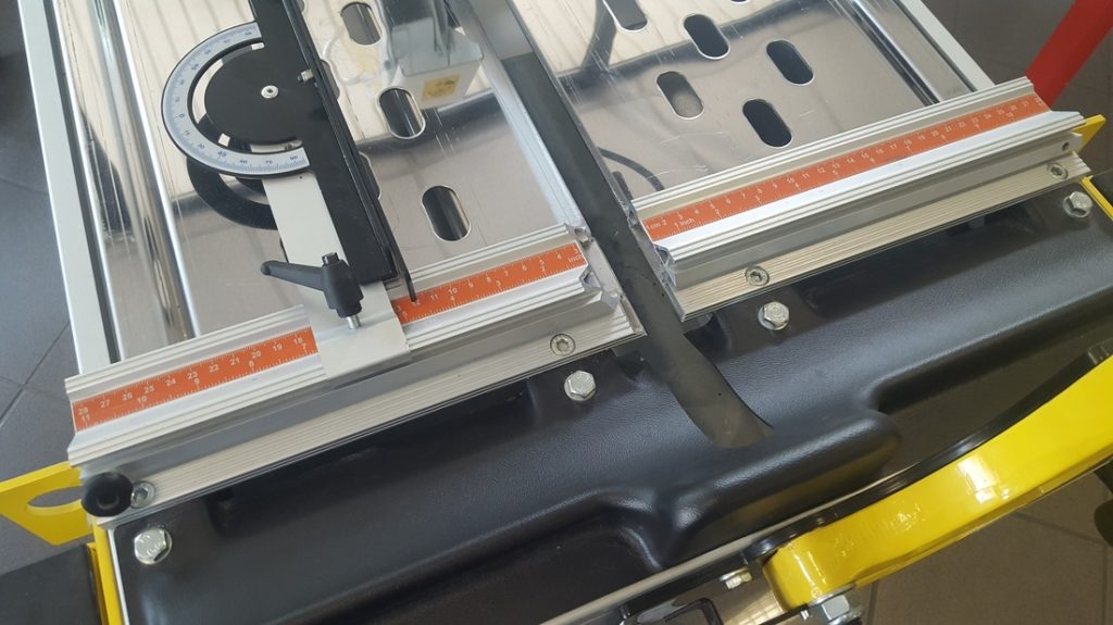
On Ghelfi Revolution family models Allen-head screws are directly visible – not hidden beneath the stuck-on ruler.
Required Allen-key size for these screws is the same accross all Ghelfi machines.
Sorry, the comment form is closed at this time.